Blog
Understanding the Flout® Dosing System for Septic Fields 02/26/2015
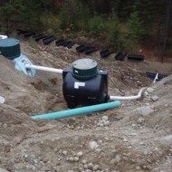
The FLOUT® Dosing System offers a simple, self-contained and trouble free method of delivering intermittent dosing to gravity fed and pressure fed septic fields. Premier FLOUT® Dosing Tanks are completely pre-assembled, dose calibrated and ready for installation.
Sites where the distribution field can be located at a lower elevation than the septic system discharge, provide the opportunity to avoid the cost and complexity of pumped delivery. This saves on standby volume, pumps, wiring, controls, installation and maintenance.
Performance in pumped systems can be fairly accurately modeled by engineering calculations, then a pump selection can be made to deliver the design performance. These calculations assume totally flooded flow in the system piping. The same principles of fluid dynamics apply to the FLOUT® system, however, potential entrapment of air in the transport pipe from the FLOUT® to the septic field will reduce flow rate and residual head compared with the theoretical maximum for a given design.
Flow rate from the FLOUT® is largely determined by:
- The vertical distance between the Dosing Tank and field. (induced flow).
- The percentage of complete flooding in the transport pipe.
- The resistance to flow at the field. That is, a small field will have a higher resistance than a larger field (with more orifice openings). Dominant variable is the total orifice area.
Squirt height will go up when the field resistance is high (small field) resulting in a lower flow rate and higher residual head. Conversely, squirt height will go down when the field resistance is low (large field) resulting in a higher flow rate and lower residual head. A double Flout® should be considered for larger fields.
Premier Plastics has carried out a series of tests to better understand the interaction between effluent and air together in the transport pipe (i.e. water wants to go down, air wants to go up) where either water flow down or air flow up could be the dominant force, or at times be equal opposing forces. Air behaviour was observed through clear acrylic tubing. Tests were carried out for 20 to 120 orifices at 1/8” dia. and 3/16” dia. Average total static head used for tests – 142” and 42”. Detailed results for specific configurations are available upon request on our website.
The data we have accumulated offers engineers and designers insight into the actual dynamics of these systems in anticipation of a greater comfort level with the selection of FLOUT® Dosing Systems. A simple method to determine feasibility for a specific site is proposed. We welcome your comments on this work.
Data provided by Premier Plastics is intended for information only. Premier Plastics does not assume any responsibility for the correctness, accuracy or interpretation of the data, or for the use of the data in system design.
FLOUT® (floating outlet) is a trade name of Rissy Plastics in Torrington CT.
John Richardson
PREMIER PLASTICS INC. March 8, 2013
FLOW OBSERVATIONS
- In smaller fields, the higher resistance to flow causes the effluent to quickly fill the transport pipe from the bottom up thus driving air out through the vent inside the dosing tank. The transport pipe then runs fully flooded producing the benefit of the full head in the system.
- In large fields, the lower resistance to flow causes the effluent to run out faster, and equilibrium between the flow in from the Flout and flow out to the field occurs before the air can be purged from the transport pipe.
- Depending on the size of the field, air will either completely purge, slowly purge over the duration of the discharge or remain trapped in the transport pipe for the duration of the discharge.
- At higher flow rates from the dosing tank a secondary effect occurs when the discharge is reaching the end of the cycle. The backed up head in the internal vent pipe reduces to the point where the high flow rate effluent sucks air into the flow thus reducing the effective head in the transport pipe. This is indicated by a slower decline in the flow rate profile.
- At the same residual head, five orifice sizes from 1/8” to 1/4” diameter demonstrated no appreciable difference in squirt height.
- The flow rate discharge profile graphs indicate the influence of air in the system.
Fully flooded flow during the whole cycle will show as a shallow decline in flow rate as the effluent level in the tank declines through the discharge cycle. The steep slope at the end of the cycle reflects drain out of the transport pipe.
A more horizontal line indicates that some air is escaping over the entire cycle thus increasing the residual head. The declining head in the tank is offset by increasing residual head.
An increasing flow rate over the entire cycle indicates that significant air is escaping throughout the cycle.
A flow rate that slopes up, then down indicates that the air has completely purged or reached a steady state part way through the cycle and then declines with the declining head in the tank.
Flow rates that show a slow decline towards the end of the cycle indicate that air is being drawn through the vent inside the tank thus reducing the residual head at the field.
Note: measurements of flow rate and residual head were taken at the entry point to the (simulated) field. Piping used for the transport pipe was 2”, 3” and 4” dia. clear acrylic.
GENERAL EFFECTS OF TRANSPORT PIPE SIZE
- A smaller diameter pipe (2”) will fully flood more quickly resulting in full benefit of the vertical head in driving the flow to the field.
- A medium diameter pipe (3”) may cause the air and effluent to remain in a turbulent interaction as equally opposing forces throughout the cycle. The flow may oscillate between fully flooded and channel flow in different sections of the pipe. This scenario may result in the most potential aeration of the effluent but squirt height will be limited. Venting the transport line near the top of the slope will expel the trapped air and result in a greater squirt height.
- A large diameter pipe (4”) will result in more stable flow – meaning channel flow (non-flooded) at the top end of the transport pipe, and fully flooded flow at the lower section which would produce the driving head into the field. There is no head benefit from non-flooded sections of pipe.
- A combination of a larger pipe diameter at the top end of the transport pipe, and smaller pipe diameter at the lower end will ensure that the required residual head for the desired squirt height is achieved. What may be deemed as too much squirt height in a system with a large vertical drop can be managed by ensuring the flow in the upper section of the transport pipe is running in channel mode with stable separation of effluent and air, thus limiting the buildup of residual head at the field.
- The maximum potential flow rate (i.e. no trapped air) was determined by pre-flooding the transport pipe prior to starting the cycle. Comparing these results with the normal cycle indicates the degree of influence of air in the transport pipe. (see Tables.)
FLOW RATE WITH MINIMAL VERTICAL DROP
Systems where fully flooded flow is necessary to maintain a desired squirt height must be designed to ensure air is purged quickly at the start of the discharge cycle. Trapped air will be at the pressure generated by the head in the Dosing tank and will act to limit flow rate. We have found that a 1” vent connection placed a few feet down the sloped section of pipe will purge air that would otherwise be trapped. At this point the effluent would have increased in speed and reverted to channel flow from fully flooded flow in the horizontal section of pipe leaving the flout. Venting the line to atmosphere reduces the ‘back pressure’ on the tank and allows trapped air to escape, and the transport pipe to flood quickly. This venting option can result in a 50% increase in squirt height.
Click here for our new flyer for type C, where the field is level with the septic tank.