Mechanical Dose Counters
Flout Dose Counter Model DC3 by Rissy Plastics, LLC
ABOUT THE COUNTER:
The DC3 Counter is a mechanical tally counter for monitoring the fill/empty cycle of a dosing chamber or similar vessel. It requires no batteries or
Flout Dose Counter Model DC3 by Rissy Plastics, LLC
ABOUT THE COUNTER:
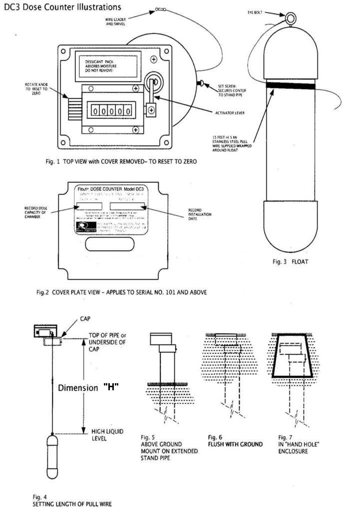
The DC3 Counter is a mechanical tally counter for monitoring the fill/empty cycle of a dosing chamber or similar vessel. It requires no batteries or wiring. It is immune to electrical surges, never forgets, and is housed in a waterproof enclosure. It is activated by a weighted float (3) suspended by a non-corrosive wire. An internal seal allows the wire to activate the counter while keeping out water and contaminates. A dessicant pouch (1) helps to minimize moisture within the enclosure. The Counter mounts on 3″ Sch 40 pipe.
MOUNTING THE COUNTER:
The Counter may be mounted inside or outside of the chamber. Brackets, pipe, fittings, and hardware are supplied by the installer.
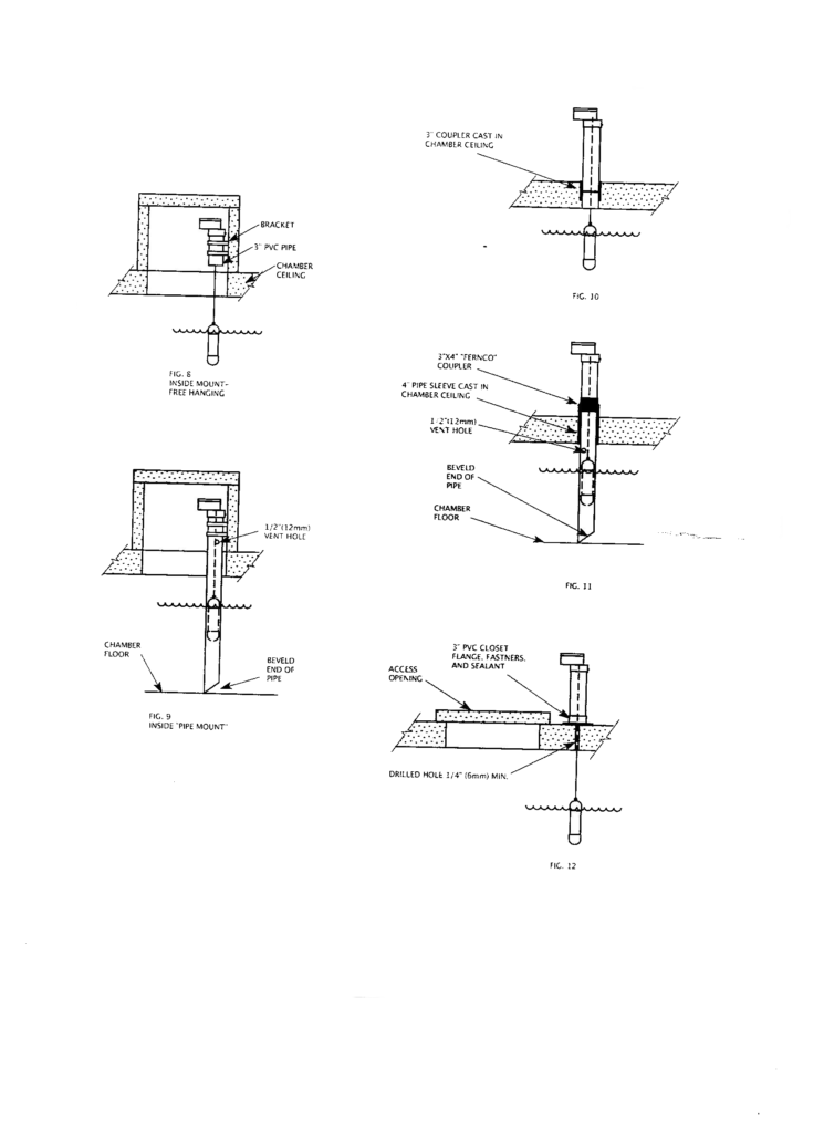
The Float (3) may hang free (8,10,12) or be “pipe mounted” inside a 3″ pipe (9,11). Pipe mounting is the preferred method if thee is turbulence or a chance of entanglement of the pull wire with other equipment in the chamber. IMPORTANT: The pipe must be vertical, must allow liquid to enter (bevel bottom), and be vented (1/2″ hole) above the highest water line to prevent an air pocket from forming (9,11).
Inside mounting may use a short piece of 3″ pvc pipe and brackets (8), or be “pipe mounted” (9).
Outside mounting requires a passage through the chamber ceiling. The Counter may be above grade on an extended stand pipe (5), flush with grade (6), or in a “Hand Hole” (7).
Passage through the chamber ceiling may be pre-cast or drilled. Some methods are: A 3 inch pipe coupler cast in (10), “pipe mounted” through a 4 inch sleeve cast in, with a 3×4 inch “Fernco” coupler (11), or free hanging through a small hole with the stand pipe attached to an overturned closet flange (12). When using a small hole, a large access hole must be nearby to attach the Float.
SETTING THE FLOAT:
A minimum of 6″ (150mm) liquid rise and drop is required for the counter to work. Contact Rissy Plastics if the drop is less. The float (3) comes with 15 feet (4.5 M) of stainless steel pull wire attached. If more is needed, use stainless steel picture wire. Splice securely. Avoid kinking the wire.
The Float must operate in the upper area of the liquid pool. If the wire is too long, jamming or tangling is possible.
Determine the dimension “H” (4) from the top of the installed standpipe to the highest liquid level. Unwind the wire and pass it through the Swivel (1). Set the wire to same dimension “H” (4) from the underside of the cap (4) to the eye bolt on the Float (3). Twist the wire multiple times and trim the excess, leaving a bit of extra wire if adjustment is needed.
Lower the Float into the stand pipe, push the cap onto the pipe, and lock with the setscrew (1). DO NOT GLUE!
If using method (12), remove the wire from Float. Attach the wire to the swivel. Mark the dimension “H”(4) on the wire with a marker or tape, pass it down the stand pipe and through the small hole. Push the cap onto the pipe, and lock with the setscrew (1). DO NOT GLUE! Using the access hole, attach the Float at the mark. Twist multiple times and trim the wire leaving a bit extra for adjustment.
TESTING:
Remove the clear cover and label plate (2) (if equipped). The activator lever (1) should be down. Test fill the chamber. The lever should rise before the chamber reaches maximum depth. If the lever does not rise, remove the Counter and increase the length of the wire. As the chamber empties, the Float will pull the lever back down, registering a count.
FINISHING UP:
Reset the counter by rotating the knob (1). Using an indelible marker, fill in the start-up date and dose capacity on the label plate (2) (if equipped). Do not remove the dessicant (1). Replace the cover. Do not overtighten the screws.
MONITORING:
Each dose cycle will raise the count by one. Multiply the count times the dose capacity to find out the amount of liquid dosed. If the system is in use but no count is registered, inspect the counter float and the operation of the dosing devices, otherwise call for service.
DC3 DOSE COUNTER ILLUSTRATIONS
To print out a pdf version of the installation instructions for Flout Dose Counter Model DC3 please click below.
DC3 Dose Counter Installation Instructions – 4 pages
Flout Dose Counter Model DC4 with LOW PROFILE ACTIVATOR INSTALLATION INSTRUCTIONS by Rissy Plastics, LLC
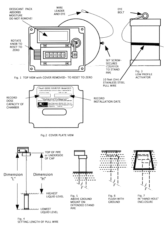
Note: Model DC4 is the same as DC3 except the profile of the activator float is changed to operate with a shorter stroke for dosing applications requiring a low drawdown.
ABOUT THE COUNTER:
The DC4 Counter is a mechanical tally counter for monitoring the fill/empty cycle of a dosing chamber or similar vessel. It requires no batteries or wiring. It is housed in a water resistant enclosure. It is controlled by a weighted “Activator” (3) suspended by a non-corrosive wire. An internal seal allows the wire to trigger the counter while keeping out water and contaminates. A dessicant pouch (1) helps to minimize moisture within the enclosure. The Counter mounts on 4″(100mm) Sch 40 pipe. A rise and fall of 3″ (75mm) is required to cycle the counter.
MOUNTING THE COUNTER:
The Counter may be mounted inside or outside of the chamber. Brackets, pipe, fittings, and hardware are supplied by the installer.
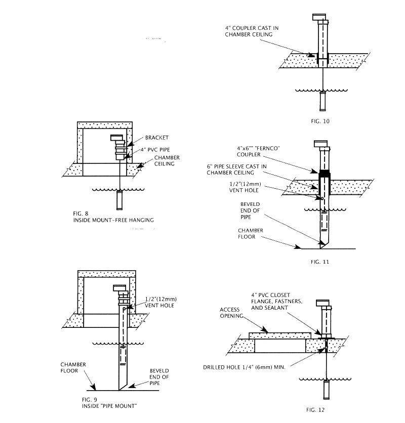
The Activator (3) may hang free (8,10,12) or be “pipe mounted” inside a 4″ pipe (9,11). Pipe mounting is the preferred method if there is a turbulence or a chance of entanglement of the pull wire with other equipment in the chamber. IMPORTANT: The pipe must be vertical, must allow liquid to enter (bevel bottom), and be vented (1/2″ hole) above the highest water line to prevent an air pocket from forming (9,11).
Inside mounting may use a short piece of 4″ pvc pipe and brackets (8), or be “pipe mounted” (9).
Outside mounting requires a passage through the chamber ceiling. The Counter may be above grade on an extended stand pipe (5), flush with grade (6), or in a “Hand Hole” (7).
Passage through the chamber ceiling may be pre-cast or drilled. Some methods are: A 4 inch pipe coupler cast in (10), “pipe mounted” through a 6 inch sleeve cast in, with a 4×6 inch “Fernco” coupler (11), or free hanging through a small hole with the stand pipe attached to an overturned closet flange (12). When using a small hole, a large access hole must be nearby to attach the Activator.
SETTING THE ACTIVATOR:
A minimum of 3″ (75mm) liquid rise and fall is required for the counter to work. The Activator (3) comes with 10 feet (3m) of stainless steel pull wire attached. If more is needed, use stainless steel picture wire. Spice securely.
The Activator is semi-buoyant and will sink on its own. As long as the bottom of the Activator is above the lowest water level and the top is below the highest level the counter will work.
Determine the dimension “H” (4) from the top of the installed standpipe to the highest liquid level. Unwind the wire and pass it through the Eye (1). Set the wire to same dimension “H” (4) from the underside of the cap (4) to the eye bolt on the Activator (3). Twist the wire multiple times and trim the excess, leaving a bit of extra wire if adjustment is needed. Dimension “L” may also be used. Set the bottom of the Activator to the lowest water level. The semi-buoyant Activator will keep the pull wire taught to prevent tangling.
Lower the Activator into the stand pipe, slip the cap onto the pipe, and lock with the setscrew (1). DO NOT GLUE!
If using method (12), remove the wire from Activator. Attach the wire to the eye. Mark the dimension “D”(4) on the wire with a marker or tape, pass it down the stand pipe and through the small hole. Place the cap onto the pipe, and lock with the setscrew (1). DO NOT GLUE! Using the access hole, attach the Float at the mark. Twist multiple times and trim the wire leaving a bit extra for adjustment.
TESTING:
Remove the clear cover and label plate (2) (if equipped). The activator lever (1) should be down. Test fill the chamber. The lever should rise before the chamber reaches maximum depth. If the lever does not rise, remove the Counter and increase the length of the wire. As the chamber empties, the Float will pull the lever back down, registering a count.
FINISHING UP:
Reset the counter by rotating the knob (1). Using an indelible marker, fill in the start-up date and dose capacity on the label plate (2) (if equipped). Do not remove the dessicant (1). Replace the cover. Do not overtighten the screws.
MONITORING:
Each dose cycle will raise the count by one. Multiply the count times the dose capacity to find out the amount of liquid dosed. If the system is in use but no count is registered, inspect the counter float and the operation of the dosing devices, otherwise call for service.
MAINTENANCE:
Little is necessary. If moisture accumulates inside, remove the cover and allow it to dry out. If the cover becomes difficult to see through from scratches and outside dirt, spray and wipe it with WD40 to clear it up.
WARNING!
Installing, servicing, and inspecting this product may involve entering confined spaces. Confined spaces may contain deadly gases and/or insufficient oxygen. Confined spaces entry requires special training, equipment, and permitting. Failure to adhere to this warning may result in injury or death. Rissy Plastics or Premier Plastics Inc. shall not be held liable for any injury or dealth resulting from any confined space entry.
To print out a pdf version of the installation instructions for Flout Dose Counter Model DC4 please click below.
DC4 Dose Counter with low profile activator Installation Instructions – 4 pages